Pitot Tube Flow Measurement
Pressure sensors are classified as Differential Pressure sensors for flow measurement.
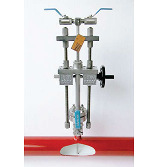
The measuring principle of the pitot tube utilizes the differences between the pressure ridge on the upstream side of a bluff body and the static pressure on its down stream side.
ITABAR-pitot tube sensors, see sample Fig 1.1, are mainly used to measure the volumetric flow of liquids, gases and steam in closed pipes ranging from ½“ to 480“ (DN 20 to DN 12000).
Examples of their applications are precise volumetric flow measurement in batch processes, continuous measurement of liquid ingredients in the process industry, fuel, air, steam and gases as primary energy source as well as in control functions requiring a high degree of stability and repeatability.
Pitot Tube Flow Measurement
<
>
Unique Sensor Profile
The design of the ITABAR-sensor profile, see Fig. 8, is optimized with respect to fluid flow properties, and meets the technical challenges of accurate measurement as well as static and sensor-oscillating problems. It represents a step forward in technical development.
Excellent Linearity
A significant improvement in the sensor design with respect to the fluid properties is the shape of the sensor profile. The fluid separation takes place at the same spot on the sensor over a wide range of Reynolds numbers, which results in minimal Reynolds number dependency. This specially designed ITABAR-sensor profile achieves excellent linearity over a wide measuring range.
Exemplary Reproducibility
The form design of the sensor profile not only improves the linearity but also the reproducibility of the measurement in cases of averaging within certain time intervals. The result is especially positive with shorter time intervals.
Superior Averaging
In order to reduce the influences of in most cases less than ideal flow profiles, the differential pressures representing the local flow velocities are measured at four points, averaged and processed. Each of these four measuring points has pressure sensing apertures located opposite from each other. The positioning of these pressure apertures is designed for fluid flow profiles as they are encountered in real applications.
Product Info
Documentation
Case Studies
Training & Support
Video
How does it work?
For a better understanding the meaing of the sensor-version nomenclature will be explained in the following. Pitot tube sensors which start with the letter „IB..“ are designed for fixed (installation not under pressure) installations. The letter „R“ („F“, „G“) indicates a threaded (flanged, welded) process
connection between the pipe and the sensor’s assembly components. All sensors, which are used to measure steam have the letter „D“ at the end of the model name. The additions „HT“ or „HTG“ stand for „High Temperature“. Pitot tube sensor series „Flo-Tap“ is indicated by the letter „FT’ at the
beginning of the model name. They can be installed and removed under pressure conditions (wet-tap design). The letters „N“ („M“, and „H“) signify their possible use in low („N“) and medium and high operating pressure applications, with „D“ for steam use. Model series 21,26,36 and 66 differ from
series 20,25,35 and 65 in that they come with a counter-end support, which serves to avoid mechanical stress caused by high flow velocities and high impact pressures or sensor-resonance oscillations
What problems does it solve?
Title
Description
Actions
Pilot Tube Flow Measurement
Introduction
Title
Description
Actions
Title
Description
Actions
No data available in table
Title
Description
Actions

Head office
1 Adeola Odeku Street
South Atlantic Petroleum Towers
Victoria Island | Lagos | Nigeria
Tel: +234 1904 9589, +234 (0) 909 026 0055
Lagos Branch Office
15, Ogundana Street | Off Allen Avenue |
Ikeja | Lagos | Nigeria
Stay Connected With Us!
GCA Energy Staff Email
Access Email Service
Port Harcourt Branch Office
15 Emeyal Street
GRA Phase I
Port Harcourt, Rivers State, Nigeria
Tel: +234 8093906260